
When you need a PCB assembled by a pick-and-place machine, you must generate a position file (also known as a component placement file) so the machine knows exactly where to place each component.
This process in KiCAD can be a little tricky, so this guide will walk you through how to correctly generate a position file to be sure of a smooth PCB assembly process.
Step 1: Set the Place File Origin
First you need to place a ‘Place File Origin’. Go to ‘Place’ and pick ‘Drill/Place File Origin’.
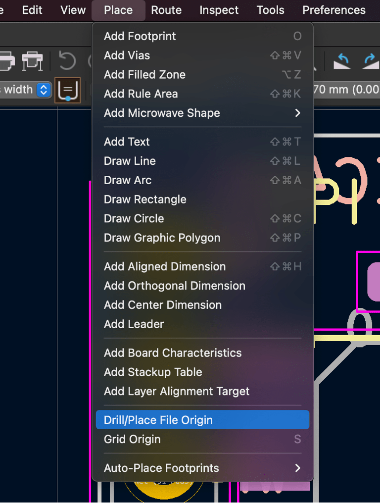
Place the origin in the lower left hand corner of your board. If it isn’t exactly perfect in the corner it is okay as long as it is close.

Step 2: Generate the Component Placement File (.pos)
In PCBNew go to ‘File’ and then ‘Fabrication Outputs’ – From there select Component Placement (.pos)…

When generating these files, make sure to use the following settings:
- Format: ASCII
- Units: Millimeters
- Files: Separate files for front, back
- Check – Use drill/place file origin

Step 3: Understand the Generated .POS Files
KiCAD will generate two ‘.pos’ files generated. One for the top of the board and one for the bottom of the board. These are the files that we need for the pick-and-place machine during PCB assembly.


Let’s take a look at what the file includes.
- Ref: The designator for the component. This is usually set in the schematic builder.
- Val: The component value. This is usually set in the schematic builder.
- Package: The footprint used in the PCB layout.
- PosX: X-Position relative to the place origin.
- PosY: Y-Position relative to the place origin.
- Rot: How many degrees should the part be rotated by the machine in assembly.
- Side: Which side of the board is this part on. You should have two separate files for the top and bottom.
Step 4: Avoid Manually Editing the .POS File
If you find that you need to change the ‘.pos’ file, it is important to not change the file that is created. Instead, make the changes directly in your PCB layout and generate a new ‘.pos’ file. The file that is generated gets fed into our pick and place machines and if you change the format, it may not work correctly, causing errors during automated assembly, as the pick-and-place software expects a specific format.
Step 5: Double-Check Before Sending to Fabrication
A properly generated position file helps avoid component misalignment, assembly delays, and costly reworks.
Generating a position file in KiCAD is a simple but important step in PCB manufacturing and assembly. Once you understand the correct settings and file structure, you’ll be able to create accurate and reliable placement files every time.

Taking your time to get this process correct will make your assembly process smoother all around.